
1-802.1Q Trunking & LACP

Tasks
Task 1. Configure the trunks between SW1 and Sw2 on ports E0/0 and E0/1 using the IEEE standard frame tagging method.
+ Only the VLANs for the PCs should be permitted across the trunks.
+ Routers are simulated as PCs and are preconfigured with IP Addresses.
+ PC configurations must remain unchanged.
Task 2. On SW1 and SW2, use IEEE 802.3ad link aggregation.
+ Assign number 10 to the link.
+ Combine E0/0 and E0/1 into a single logical link.
+ Both links must negotiate aggregation.
Configuration
On both SW1 & SW2:
SW1,SW2(config)#interface range e0/0 – 1
SW1,SW2(config-if-range)#switchport trunk encapsulation dot1q
SW1,SW2(config-if-range)#switchport mode trunk
SW1,SW2(config-if-range)#switchport trunk allowed vlan 10,30
SW1,SW2(config)#interface range e0/0 – 1
SW1,SW2(config-if-range)#channel-group 10 mode active
SW1#show etherchannel summary
PC1#ping 10.2.2.20
2-802.1Q Trunking & LACP

Tasks
Task 1. Configure trunks between Sw1 and Sw2 on ports E0/0 and E0/1 using the IEEE standard frame tagging method.
– Add VLAN 45 as untagged on the trunk ports.
– Only extend VLAN 15 and the untagged VLAN across the trunk.
– Verify that PC1 is capable of pinging PC2.
Task 2. On Sw1 and Sw2, use IEEE 802.3ad link aggregation.
– Combine E0/0 and E0/1 into a single logical link while leaving the trunk configurations intact
– Assign number 15 to the link.
– Both links must negotiate aggregation.
Configuration
Task1
On both Sw1 & Sw2:
Sw1,Sw2(config)#interface range e0/0 – 1
Sw1,Sw2(config-if-range)#switchport trunk encapsulation dot1q
Sw1,Sw2(config-if-range)#switchport mode trunk
Sw1,Sw2(config-if-range)#switchport trunk native vlan 45
Sw1,Sw2(config-if-range)#switchport trunk allowed vlan 15,45
Verification
PC1#ping 10.15.15.20
.!!!!
Task 2.
interface range e0/0 – 1
Sw1,Sw2(config-if-range)#channel-group 15 mode active
Verification
show etherchannel summary
3-Voice VLAN & LLDP Sim

Tasks
All physical cabling is in place and verified. Connectivity for the Switches on ports E0/1, E0/2, and E0/3 must be configured and available for voice and data capabilities.
1. Configure Sw1 and Sw2 with both VLANS, naming them according to the VLAN Name provided in the topology.
2. Configure the E0/1, E0/2, and E0/3 ports on both switches for both VLANS and ensure that Cisco IP phones and PCs pass traffic.
3. Configure Sw1 and Sw2 to allow neighbor discovery via the vendor-neutral protocol on e0/0.
Configuration
Task 1.
On both switches:
Sw1,Sw2(config)#vlan 77
Sw1,Sw2(config-vlan)#name User_VLAN
Sw1,Sw2(config-vlan)#vlan 177
Sw1,Sw2(config-vlan)#name Voice_VLAN
Sw1,Sw2(config-vlan)#exit
Task 2.
On both switches:
Sw1,Sw2(config)#int range e0/1 – 3
Sw1,Sw2(config-if)#switchport mode access
Sw1,Sw2(config-if)#switchport access vlan 77
Sw1,Sw2(config-if)#switchport voice vlan 177
Task 3.
On both switches:
Sw1,Sw2(config)#lldp run
Sw1,Sw2(config)#int e0/0
Sw1,Sw2(config-if)#lldp transmit
Sw1,Sw2(config-if)#lldp receive
Verification
On either switch:
SW-1#show lldp neighbors
4-IPV4 IPV6 Address Assignment [New]

Tasks
Reference Topology Diagram and table. Configure IPv4 and IPv6 between the two routers.
Task 1:
+ Configure R1 with the first usable host IP address in the IPv4 network.
+ Configure R2 with the last usable host IP address in the IPv4 network.
+ Verify connectivity using ping.
Task 2:
+ Do not assign the subnet router anycast address to either router.
+ Configure R1 with the first usable host IP address in the IPv6 network.
+ Configure R2 with the last usable host IP address in the IPv6 network.
+ Verify connectivity using ping.
Configuration
R1(config)#interface e0/0
R1(config-if)#ip address 10.0.12.5 255.255.255.252
R1(config-if)#no shut
R2(config)#interface e0/0
R2(config-if)#ip address 10.0.12.6 255.255.255.252
R2(config-if)#no shut
+ Verify connectivity using ping.
R1(config-if)#exit
R1(config)#exit
R1#ping 10.0.12.6
.!!!! -> ping successful
R1(config)#interface e0/0
R1(config-if)#ipv6 address 2001:db8:12::1/126
R2(config)#interface e0/0
R2(config-if)#ipv6 address 2001:db8:12::3/126
+ Verify connectivity using ping.
R1#ping 2001:db8:12::3
!!!!! -> successful
5-Static Routing [New]

Tasks
Task 1
+ Configure a host route on R5 for the destination of 10.200.220.6.
+ Configure a static default route on R1 preferring the path through R3 towards R6.
+ From R5, use traceroute and ping to verify the path towards and reachability of R6.
Task 2
+ Configure a floating static default route on R1, preferring the path through R2 towards R6 if the link to R3 should fail.
+ Configure the administrative distance for 225.
+ Configure a static route on R2 to forward the return traffic towards 10.100.110.0/25.
+ After shutting interface e0/1 on R1, use traceroute and ping from R5 to verify path towards and reachability of R6.
Configuration
R5(config)#ip route 10.200.220.6 255.255.255.255 10.100.110.1
R1(config)#ip route 0.0.0.0 0.0.0.0 10.133.13.3
R5(config)#exit
R5#ping 10.200.220.6
.!!!! -> successful
R1(config)#ip route 0.0.0.0 0.0.0.0 10.122.12.2 225
R2(config)#ip route 10.100.110.0 255.255.255.128 10.122.12.1
R1(config)#interface e0/1
R1(config-if)#shut
R1(config-if)#exit
R1(config)#exit
R5(config)#exit
R5#ping 10.200.220.6
!!!!! -> successful
R5#traceroute 10.200.220.6
Type escape sequence to abort.
Tracing the route to traceroute 10.200.220.6
1 10.100.110.1 0 msec 0 msec 0 msec //R1
2 10.122.12.2 0 msec 0 msec 0 msec //R2
3 10.240.24.4 0 msec 0 msec 0 msec //R4
4 10.200.220.6 0 msec 0 msec 0 msec //R6
Do not forget to use WR for save on R5 , R1, R2
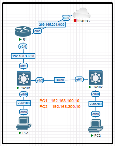
6-OSPF Routing [New]

Tasks
Task 1. Configure OSPF Area 0 with Process ID 110 on all devices under their respective interfaces connected to VLAN101.
To accomplish this, do not use the network command under the OSPF process.
Task 2. Configure R1 to always be the DR and Sw101 always to be the BDR.
R2 and R3 should be configured not to participate in the DR/BDR election.
Configuration
On R1:
R1(config)#interface e0/2
R1(config-if)#ip ospf 110 area 0
On R2:
R2(config)#interface e0/1
R2(config-if)#ip ospf 110 area 0
On R3:
R3(config)#interface e0/0
R3(config-if)#ip ospf 110 area 0
On Sw101:
Sw101(config)#interface vlan101
Sw101(config-if)#ip ospf 110 area 0
Verification
SW101#sh ip ospf neighbor
Neighbor ID Pri State
10.3.3.3 1 FULL/BDR
10.1.1.1 1 FULL/DROTHER
10.2.2.2 1 FULL/DROTHER
On R1 (Suppose we are still under interface E0/2):
R1(config-if)#ip ospf priority 255
On Sw101 (Suppose we are still under interface Vlan101):
Sw101(config-if)#ip ospf priority 254
On R2 (Suppose we are still under interface E0/1):
R2(config-if)#ip ospf priority 0
On R3 (Suppose we are still under interface E0/0):
R3(config-if)#ip ospf priority 0
We should clear the OSPF process on Sw101 to see the result:
On Sw101
Sw101(config-if)#exit
Sw101(config)#exit
Sw101#clear ip ospf process
Reset ALL OSPF processes? [no]: y
7-OSPF 2 Routing [New]

Tasks
Refer to the topology. All physical cabling is in place. Routers 2 and 3 are inaccessible. Configure OSPF routing for the network and ensure R1 has joined Area 0 without using network statements.
Task 1. Configure OSPF on R1 with a process ID and router- ID only as follows:
– use process ID 33
– use E0/1 IP as the router ID
Task 2
– Configure R1 to establish neighbor adjacencies with R2 and R3. The network statement under the OSPF process must not be used.
– Configure R1 to always become the DR for Area 0
Configuration
On R1:
R1(config)#router ospf 33
R1(config-router)#router-id 10.0.33.1
Task 2
– Configure R1 to establish neighbor adjacencies with R2 and R3.
The network statement under the OSPF process must not be used.
– Configure R1 to always become the DR for Area 0
On R1:
R1(config-router)#exit
R1(config)#interface e0/0
R1(config-if)#ip ospf 33 area 0
R1(config-if)#ip ospf priority 255
R1(config-if)#interface e0/1
R1(config-if)#ip ospf 33 area 0
R1(config-if)#ip ospf priority 255
Verification
We should clear the current OSPF process to make sure DR is elected again.
R1(config-if)#exit
R1(config)#exit
R1#clear ip ospf process
Reset ALL OSPF processes? [no]: y
Then verify with the “show ip ospf neighbor” or “show ip ospf interface” command:
R1#show ip ospf neighbor
Neighbor ID Pri State Dead Time
10.2.2.2 1 FULL/BDR 00:00:35
10.3.3.3 1 FULL/BDR 00:00:35
8-VLAN CDP LLDP LAB 1
Tasks
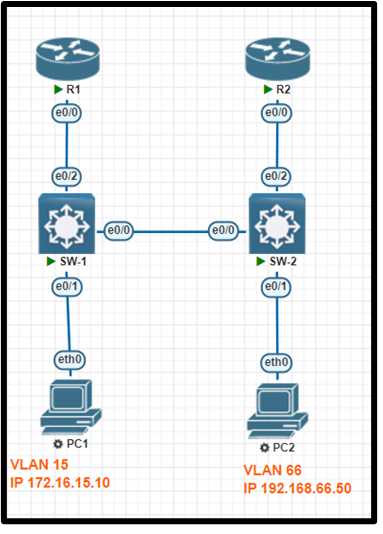
R1 and R2 are pre-configured with all the necessary commands. All physical cabling is in place and verified. Connectivity for PC1 and PC2 must be established to the switches; each port must only allow one VLAN and be operational.
1. Configure SW-1 with VLAN 15 and label it exactly as OPS
2. Configure SW-2 with VLAN 66 and label it exactly as ENGINEERING
3. Configure the switch port connecting to PC1.
4. Configure the switch port connecting to PC2.
5. Configure the E0/2 connections on SW-1 and SW-2 for neighbor discovery using the vendor-neutral standard protocol and ensure that e0/0 on both switches uses the Cisco proprietary protocol
Configuration
SW-1>en
SW-1#config t
SW-1(config)# lldp run
SW-1(config)# vlan 15
SW-1(config-vlan)# name OPS
SW-1(config-vlan)#int f0/1
SW-1(config-if)#switchport mode access
SW-1(config-if)#switchport access vlan 15
SW-1(config-if)#int f0/2
SW-1(config-if)#no cdp enable
SW-1(config-if)#lldp transmit
SW-1(config-if)#lldp receive
SW-1(config-if)#int f0/10
SW-1(config-if)#switchport trunk encapsulation isl
SW-1(config-if)#switchport mode trunk
SW-1(config-if)#end
SW-1#wr
SW-2:
SW-2>en
SW-2#config t
SW-2(config)# lldp run
SW-2(config)# vlan 66
SW-2(config-vlan)# name ENGINEERING
SW-2(config-vlan)#int f0/1
SW-2(config-if)#switchport mode access
SW-2(config-if)#switchport access vlan 66
SW-2(config-if)#int f0/2
SW-2(config-if)#no cdp enable
SW-2(config-if)#lldp transmit
SW-2(config-if)#lldp receive
SW-2(config-if)#int f0/10
SW-2(config-if)#switchport trunk encapsulation isl
SW-2(config-if)#switchport mode trunk
SW-2(config-if)#end
SW-2#wr
9-Trunking and Etherchannel LAB 2

All physical cabling is in place and verified. Connectivity between all four switches must be established and operational. All ports are pre-configured as 802. 1q trunks.
- Configure both SW-1 and SW-2 ports e0/1 and e0/2 to permit only the allowed VLANs.
- Configure both SW-3 and SW-4 ports e0/2 to permit only the allowed VLANs.
- Configure both SW-1 and SW-2 e0/1 ports to send and receive untagged traffic over VLAN 99.
- Configure both SW-3 and SW-4 ports e0/0 and e0/1 for link aggregation using the industry standard protocol. All ports must immediately negotiate the link aggregation.
- Permit only the allowed VLANs on the new link.
Configuration
SW-1:
SW-1>en
SW-1# Config t
SW-1(config)# int range f0/1-2
SW-1(config-if) # switchport trunk allowed vlan 56,77,99
SW-1(config-if) #exit
SW-1(config)# int f0/1
SW-1(config-if) # switchport trunk native vlan 99
SW-1(config-if) # end
SW-1# wr
SW-2:
SW-2>en
SW-2# Config t
SW-2(config)# int range f0/1-2
SW-2(config-if) # switchport trunk allowed vlan 56,77,99
SW-2(config-if) #exit
SW-2(config)# int f0/1
SW-2(config-if) # switchport trunk native vlan 99
SW-2(config-if) # end
SW-2# wr
SW-3:
SW-3>en
SW-3# Config t
SW-3(config)# int range f0/1,f0/10
SW-3(config-if) # channel-group 34 mode active
SW-3(config-if) #exit
SW-4(config)# int po34
SW-4(config-if) # switchport trunk allowed vlan 56,77,99
SW-4(config)# int f0/2
SW-4(config-if) # switchport trunk allowed vlan 56,77,99
SW-3(config-if) # end
SW-3# wr
SW-4:
SW-4>en
SW-4# Config t
SW-4(config)# int range f0/1,f0/10
SW-4(config-if) # channel-group 34 mode active
SW-4(config-if) #exit
SW-4(config)# int po34
SW-4(config-if) # switchport trunk allowed vlan 56,77,99
SW-4(config)# int f0/2
SW-4(config-if) # switchport trunk allowed vlan 56,77,99
SW-4(config-if) # end
SW-4# wr
10-VLAN And LLDP new LAB 3
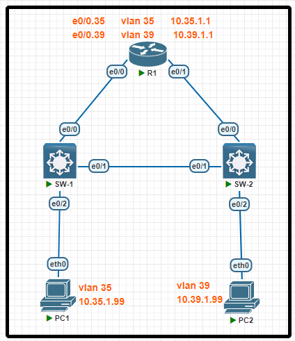
R1 has been pre-configured with all the necessary commands. All physical cabling is in place and verified. Connectivity for PC1 and PC2 must be established for the switches, and each port must only allow one VLAN
- Configure SW-1 with VLAN 35 and label it exactly as SALES
- Configure SW-2 with VLAN 39 and label it exactly as MARKETING
- Configure the switch port connecting to PC1
- Configure the switch port connecting to PC2
- Configure SW-1 and SW-2 for universal neighbor discovery using the industry standard protocol and disable it on the interface connecting to PC1.
Configuration
SW-1> en
SW-1# conf t
SW-1 (config)#no cdp run
SW-1 (config)#lldp run
SW-1 (config)#vlan 35
SW-1 (config)#name SALES
SW-1 (config)#int f0/2
SW-1 (config)# sw mode acc
SW-1 (config)#sw acc vlan 35
SW-1 (config)#no lldp transmit
SW-1 (config)#no lldp receive
SW-1 (config)#end
SW-1# wr
SW-2> en
SW-2# conf t
SW-2 (config)#no cdp run
SW-2 (config)#lldp run
SW-2 (config)#vlan 39
SW-2 (config)#name MARKETING
SW-2 (config)#int f0/2
SW-2 (config)# sw mode acc
SW-2 (config)#sw acc vlan 39
SW-2 (config)#end
SW-2# wr
11-Access List DHCP Snooping LAB 4

Tasks Refer to the topology. All physical cabling is in place. configure local user account, configure a Named ACL (NACL), and Dynamic Arp Inspection.
1. Configure a local account on Sw3 with telnet access only on virtual ports 0-4. Use the following information:
Username: techl2
Password: load1key
Algorithm type: md5
Privilege level: Exec mode
2. Configure and apply a NACL on R1 to control network traffic towards ISP:
Name: ISP_ACL
Restrict RFC 1918 class A and B addresses
Allow all other addresses
3. A DHCP IP Pool is preconfigured on R1 for VLAN 5, and DHCP Snooping is configured on Sw2.
Configure on Sw2: Dynamic Arp Inspection for VLAN 5
Enable validation of the ARP packet destination MAC address
Enable validation of the ARP packet source MAC address
Enable validation of the ARP Packet IP address
Configuration
R1.
R1>en
R1#config t
R1(config)#ip access-list extended ISP_ACL
R1(config-ext-nac1)#deny ip 10.0.0.0 0.255.255.255 any
R1(config-ext-nac1)#deny ip 172.16.0.0 0.15.255.255 any
R1(config-ext-nac1)#permit ip any any
R1(config-ext-nac1)#exit
R1(config)#int g0/2
R1(config-if)#ip access-group ISP_ACL out
R1(config-if)#end
R1#wr
Sw2:
Sw2>en
Sw2#config t
Sw2(config)#ip arp inspection vlan 5
Sw2(config)#ip arp inspection validate ip src-mac dst-mac
Sw2(config)#end
Sw2#wr
Sw3:
Sw3>en
Sw3#config t
Sw3(config)#username tech12 privilege 15 secret load1key
Sw3(config)#line vty 0 4
Sw3(config-line)#login local
Sw3(config-Iine)#transport input telnet
Sw3(config-line)#end
Sw3#wr
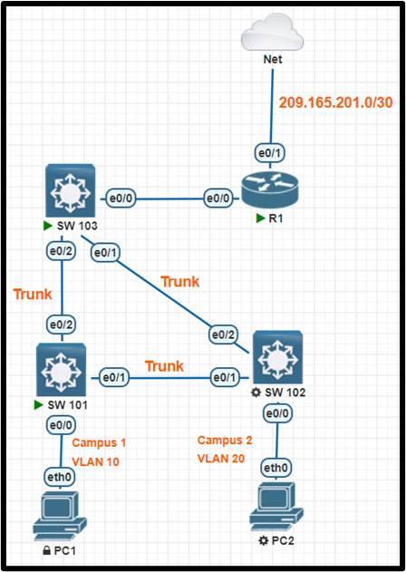
12-VLAN, LLDP, and CDP LAB 5
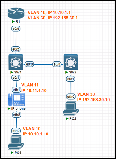
R1 has been pre-configured with all the necessary commands. All physical cabling is in place and verified. Connectivity to the end devices must be configured.
- Configure SW-1 switch port E0/1 to carry traffic for the Cisco IP phone and PC2.
- Configure SW-2 E0/1 to carry traffic for PC2.
- Configure VLAN 10 with the name “Engineering” on SW-1.
- Configure the link between SW-1 and SW-2 to use the vendor neutral neighbor discovery protocol
- Configure the link on SW-1 to R1 so that it does not allow the Cisco neighbor discovery protocol to pass
Configuration
SW-1:
SW-1>en
SW-1# Config t
SW-1(config)# vlan 10
SW-1(config-vlan)# name Engineering
SW-1(config-vlan)#int f0/10
SW-1(config-if)#lldp transmit
SW-1(config-if)#lldp receive
SW-1(config-if)#int f0/1
SW-1(config-if)#switchport mode access
SW-1(config-if)#switchport access vlan 10
SW-1(config-if)#switchport voice vlan 11
SW-1(config-if)#int f0/2
SW-1(config-if)#no cdp enable
SW-1(config-if)#end
SW-1#wr
SW-2:
SW-2>en
SW-2# Config t
SW-2(config)#int f0/10
SW-2(config-if)#lldp transmit
SW-2(config-if)#lldp receive
SW-2(config-if)#int f0/1
SW-2(config-if)#switchport mode access
SW-2(config-if)#switchport access vlan 30
SW-2(config-if)#end
SW-2#wr
13-Trunking and ether-channel LAB

Tasks
vlan 35 and vlan 45 have been configured in three switches all physical connectivity has been installed and verified all inter-switch link must be operational
1-configure SW-1 and SW-2 switch ports e0/0 and e0/1 for 802.1q trunking allowing all vlans
2- configure the inter-switch link on Sw-1 e0/2 and SW-2 e0/2 and SW-3 e0/0 , e0/1 to use native vlan 35
3- configure SW-1 and SW-2 switchport e0/0 and e0/1 for link aggregation SW-1 should immediatly negotiate LACP and SW-2 must only respond requests
Configuration
SW1> en
SW1# conf t
SW1(config)# int range f0/1-2, f0/10
Sw1(config-if-range)# sw trunk enc dot1q
Sw1(config-if-range)# sw mode trunk
Sw1(config-if-range)# int range f0/1, f0/10
Sw1(config-if-range)# channel-group 12 mode active
Sw1(config-if-range)# int f0/2
Sw1(config-if-range)# sw trunk native vlan 35
Sw1(config-if)# end
Sw1# wr
SW2> en
SW2# conf t
SW2(config)# int range f0/1-2, f0/10
Sw2(config-if-range)# sw trunk enc dot1q
Sw2(config-if-range)# sw mode trunk
Sw2(config-if-range)# int range f0/1, f0/10
Sw2(config-if-range)# channel-group 12 mode passive
Sw2(config-if-range)# int f0/2
Sw2(config-if-range)# sw trunk native vlan 35
Sw2(config-if)# end
Sw2# wr
SW3> en
SW3# conf t
SW3(config)# int range f0/1, f0/10
Sw3(config-if-range)# sw trunk enc dot1q
Sw3(config-if-range)# sw mode trunk
Sw3(config-if-range)# sw trunk native vlan 35
Sw3(config-if)# end
Sw3# wr
14-Trunk and Ether-channel LAB

Tasks All physical cabling is in place and verified. Router R1 is configured and passing traffic for VLANs 5 and 6. All relevant ports are pre-configured as 8021q trunks.
1. Configure SW-1 port E0/0 to permit only VLANs 5 and 6
2. Configure both SW-1 and SW-2’s E0/1 ports to send and receive untagged traffic over VLAN 77
3. Configure SW-2 E0/2 port to permit only VLAN 6
4. Configure both SW-3 and SW-4 ports e0/0 and e0/1 for link aggregation using the industry standard protocol with the following requirements:
• SW-3 ports must immediately negotiate the aggregation protocol
• SW-4 ports must not initiate the negotiation for the aggregation protocol
• Use the designated number assignment
Configuration
SW-1
SW-1 >en
SW-1#config t
SW-1(config)#int f0/10
SW-1(config-if)#switchport trunk allowed vlan 5,6
SW-1(config-if)#int f0/1
SW-1(config-if)#switchport trunk native vlan 77
SW-1(config-if)#end
SW-1#wr
SW-2:
SW-2>en
SW-2#config t
SW-2(config)#int f0/1
SW-2(config-if)#switchport trunk native vlan 77
SW-2(config-if)#int f0/2
SW-2(config-if)#switchport trunk allowed vlan 6
SW-2(config-if)#end
SW-2#wr
SW-3:
SW-3>en
SW-3#config t
SW-3(config)#int range f0/10,f0/1
SW-3(config-if-range)#channel-group 34 mode active
SW-3(config-if-range)#end
SW-3#wr
SW-4:
SW-4>en
SW-4#config t
SW-4(config)#int range f0/10,f0/1
SW-4(config-if-range)#channel-group 34 mode passive
SW-4(config-if-range)#end
SW-4#wr
15-VLAN Trunking LAB

Tasks
All physical cabling is in place and verified. Connectivity for PC1, PC2 and PC3 must be established to the switches. Each port connecting to the PCs must be configured as an end-user port and only allow the designated VLAN.
1. Configure VLAN 99 on all three switches and label it exactly as FINANCIAL
2. Configure the switch ports connecting to PC1, PC2 andPC3
3. Cisco’s neighbor discovery protocol has been disabled on SW-1 and must be re-enabled
4. PC1 must not be able to discover SW-1
Configuration
SW-1:
SW-1 >en
SW-1#config t
SW-1(config)#cdp run
SW-1(config)#vlan 99
SW-1(config-vlan)#name FINANCIAL
SW-1(config-vlan)#exit
SW-1(config-if)#int range f0/10,f0/1
SW-1(config-if-range)#switchport trunk encapsulation dot1q
SW-1(config-if-range)#switchport mode trunk
SW-1(config-if-range)#no shutdown
SW-1(config-if-range)#int f0/2
SW-1(config-if)#switchport mode access
SW-1(config-if)#switchport access vlan 99
SW-1(config-if)#no cdp enable
SW-1(config-if)#no shutdown
SW-1(config-if)#end
SW-1#wr
SW-2:
SW-2>en
SW-2#config t
SW-2(config)#vlan 99
SW-2(config-vlan)#name FINANCIAL
SW-2(config-vlan)#exit
SW-2(config-if)#int range f0/10,f0/1
SW-2(config-if-range)#switchport trunk encapsulation dot1q
SW-2(config-if-range)#switchport mode trunk
SW-2(config-if-range)#no shutdown
SW-2(config-if-range)#int f0/2
SW-2(config-if)#switchport mode access
SW-2(config-if)#no shutdown
SW-2(config-if)#end
SW-2#wr
SW-3:
SW-3>en
SW-3#config t
SW-3(config)#vlan 99
SW-3(config-vlan)#name FINANCIAL
SW-3(config-vlan)#exit
SW-3(config-if)#int range f0/10,f0/1
SW-3(config-if-range)#switchport trunk encapsulation dot1q
SW-3(config-if-range)#switchport mode trunk
SW-3(config-if-range)#no shutdown
SW-3(config-if-range)#int f0/2
SW-3(config-if)#switchport mode access
SW-3(config-if)#switchport access vlan 99
SW-3(config-if)#no shutdown
SW-3(config-if)#end
SW-3#wr
16-IPv4 static and default LAB

Refer to the topology. All physical cabling is in place. Routers R3 and R4 are fully configured and inaccessible. Configure static routes for various connectivity to the ISP and the LAN. which resides on R4
1. Configure a default route on R2 to the ISP
2. Configure a default route on R1 to the ISP
3. Configure R2 with a route to the Server at 10.0.41.10
4. Configure R1 with a route to the LAN that prefers R3 as the primary path to the LAN
Configuration
R1:
R1>en
R1#conf t
R1(config)# ip route 0.0.0.0 0.0.0.0 10.0.12.4
R1(config)# ip route 10.0.41.0 255.255.255.0 10.0.13.3
R1(config)# ip route 10.0.41.0 255.255.255.0 10.0.12.2 2
R1(config)# end
R1#wr
R2:
R2>en
R2#conf t
R2(config)# ip route 0.0.0.0 0.0.0.0 209.165.200.225
R2(config)# ip route 10.0.41.10 255.255.255.255 10.0.24.4
R2(config)# end
R2#wr
17-Trunking LACP

Tasks All physical cabling is in place and verified. Switch SW-1 is pre-configured and inaccessible. SW-2 and SW-3 ports must be configured and operational to complete the configuration
1. Configure SW-2 and SW-3 ports E0/0 to use the industry standard encapsulation method for trunking and only tag VLAN 10
2. Configure SW-2 and SW-3 ports E0/0 to send and receive untagged traffic over VLAN 11
3. Configure SW-2 and SW-3 ports E0/2 and E013 to use the industry standard encapsulation method for trunking and tag all VLANS
4. Configure SW-2 and SW-3 ports E012 and E0/3 for link aggregation using the industry standard protocol with the following requirements:
• SW-2 ports must not initiate the negotiation for the aggregation protocol
• SW-3 ports must immediately negotiate the aggregation protocol
• Use the designated number assignment
Configuration
SW-2>en
SW-2#config t
SW-2(config)#int range f0/10,f0/2-3
SW-2(config-if-range)#switchport trunk encapsulation dot1q
SW-2(config-if-range)#switchport mode trunk
SW-2(config-if-range)#int f0/10
SW-2(config-if)#switchport trunk allowed vlan 10
SW-2(config-if)#switchport trunk native vlan 11
SW-2(config-if)#int range f0/2-3
SW-2(config-if-range)#channel-group 23 mode passive
SW-2(config-if-range)#end
SW-2#wr
SW-3:
SW-3>en
SW-3#config t
SW-3(config)#int range f0/10,f0/2-3
SW-3(config-if-range)#switchport trunk encapsulation dot1q
SW-3(config-if-range)#switchport mode trunk
SW-3(config-if-range)#int f0/10
SW-3(config-if)#switchport trunk allowed vlan 10
SW-3(config-if)#switchport trunk native vlan 11
SW-3(config-if)#int range f0/2-3
SW-3(config-if-range)#channel-group 23 mode active
SW-3(config-if-range)#end
SW-3#wr
18-Trunking LACP LAB

Tasks SW-3 and SW-4 are preconfigured with all necessary commands. All physical cabling is in place and verified. All connectivity must be operational.
1. Configure both SW-1 and SW-2 switch ports e0/0 and e0/1 for 802.1q trunking with only VLANS 1. 12. and 22 permitted
2. Configure SW-1 port e0/2 for 802.1q trunking and include only VLANS 12 and 22
3. Configure both SW-1 and SW-2 switch ports e0/0 and e0/1 for link aggregation using the industry standard protocol. All ports must be configured so that they immediately negotiate the link
Configuration
SW-1 >en
SW-1#config t
SW-1(config)#int range f0/10,f0/1
SW-1(config-if-range)#switchport trunk encapsulation dot1q
SW-1(config-if-range)#switchport mode trunk
SW-1(config-if-range)#switchport trunk allowed vlan 1,12,22
SW-1(config-if-range)#channel-group 12 mode active
SW-1(config-if-range)#int f0/2
SW-1(config-if)#switchport trunk allowed vlan 12,22
SW-1(config-if)#end
SW-1#wr
SW-2:
SW-2>en
SW-2#config t
SW-2(config)#int range f0/10,f0/1
SW-2(config-if-range)#switchport trunk encapsulation dot1q
SW-2(config-if-range)#switchport mode trunk
SW-2(config-if-range)#switchport trunk allowed vlan 1,12,22
SW-2(config-if-range)#channel-aroup 12 mode active
SW-2(config-if-range)#end
SW-2#wr
IPv4 IPv6 LAB 12 (OLD)
Tasks
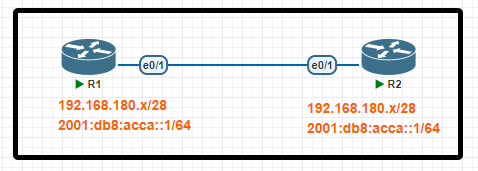
Configure IPv4 and IPv6 connectivity between two routers. For IPv4, use a /28 network from the 192.168.180.0/24 private range. For IPv6, use the first/64 subnet from the 2001:0db8:acca::/48 subnet.
1. Using Ethernet0/1 on routers R1 and R2, configure the next usable /28 from the 192.168.180.0/24 range. The network 192.168.180.0/28 is unavailable.
2. For the IPv4 /28 subnet, router R1 must be configured with the first usable host address.
3. For the IPv4 /28 subnet, router R2 must be configured with the last usable host address.
4. For the IPv6 /64 subnet, configure the routers with the IP addressing provided from the topology.
5. A ping must work between the routers on the IPv4 and IPv6 address ranges.
Configuration
R1
Enable
Conf t
Ipv6 unicast-routing
Interface G0/1
Ip address 192.168.180.17 255.255.255.240
Ipv6 enable
Ipv6 address 2001:db8:acca::1/64
No shutdown
End
Wr
R2
Enable
Conf t
Ipv6 unicast routing
Interface G0/1
Ip address 192.168.180.30 255.255.255.240
Ipv6 enable
Ipv6 address 2001:db8:acca::2/64
No shutdown
End
Wr
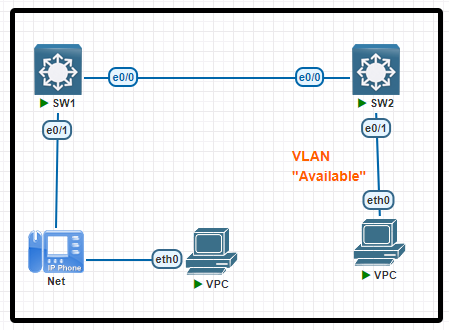
VLAN Voice LAB 13 OLD
Tasks
Tasks
All physical cabling between the two switches is installed. Configure the network connectivity between the switches using the designated VLANs and interfaces.
1. Configure VLAN 12 named Compute and VLAN 34 named Telephony where required for each task.
2. Configure Ethernet0/1 on SW2 to use the existing VLAN named Available.
3. Configure the connection between the switches using access ports.
4. Configure Ethernet0/1 on SW1 using data and voice VLANs.
5. Configure Ethernet0/1 on SW2 so that the Cisco proprietary neighbor discovery protocol is turned off for the designated interface only.
Configuration
SW1:
SW1>enable
SW 1#config t
SW1(config)#vlan 12
SW1(config-vlan)#name Compute
SW1(config-vlan)#vlan 34
SW1(config-vlan)#name Telephone
SW1(config-vlan)#int f0/10
SW1(config-if)#switchport mode access
SW1(config-if)#switchport access vlan 12
SW1(config-if)#int f0/1
SW1(config-if)#switchport mode access
SW1(config-if)#switchport access vlan 12
SW1(config-if)#switchport voice vlan 34
SW 1(config-if)#end
SW1#wr
SW2:
SW2>enable
SW2# config t
SW2(config}#vlan 12
SW2(config-vlan)#name Compute
SW2(config-vlan)#vlan 34
SW2(config-vlan)#name Telephone
SW2(config-vlan)#int f0/10
SW2(config-if)#switchport mode access
SW2(config-if)#switchport access vlan 12
SW2(config)#int f0/1
SW2(config-if)#switchport mode access
SW2(config-if)#switchport access vlan 99
SW2(config-if)#no cdp enable
SW2(config-if)#end
SW2#wr
NAT DHCP NTP SSH LAB 14 OLD
Tasks
Connectivity between three routers has been established, and IP services must be configured in the order presented to complete the implementation. Tasks assigned include configuration of NAT, NTP, DHCP, and SSH services.
1. All traffic sent from R3 to the R1 Loopback address must be configured for NAT on R2. All source addresses must be translated from R3 to the IP address of Ethernet0/0 on R2, while using only a standard access list named NAT. To verify, a ping must be successful to the R1 Loopback address sourced from R3. Do not use NVI NAT configuration.
2. Configure R1 as an NTP server and R2 as a client, not as a peer, using the IP address of the R1 Ethernet0/2 interface. Set the clock on the NTP server for midnight on January 1, 2019.
3. Configure R1 as a DHCP server for the network 10.1.3.0/24 in a pool named NETPOOL. Using a single command, exclude addresses 1-10 from the range. Interface Ethernet0/2 on R3 must be issued the IP address of 10.1.3.11 via DHCP.
4. Configure SSH connectivity from R1 to R3, while excluding access via other remote connection protocols. Access for user netadmin and password N3t4ccess must be set on router R3 using RSA and 1024 bits. Verify connectivity using an SSH session from router R1 using a destination address of 10.1.3.11. Do NOT modify console access or line numbers to accomplish this task.
Configuration
Task 1:
R2(config)# ip access-list standard NAT
R2(config-std-nacl)#permit 10.2.3.3
R2(config-std-nacl)#permit 192.168.3.1
R2(config-std-nacl)#permit 10.1.3.11
R2(config-std-nacl)#exit
R2(config)# interface G0/1
R2(config-if)#ip nat inside
R2(config-if)#exit
R2(config)#interface G0/0
R2(config-if)#ip nat outside
R2(config-if)#exit
R2(config)#ip nat inside source list NAT interface g0/0 overload
Verification
R3#ping 192.168.1.1
.!!!! (ping should work)
Task 2:
R1#clock set 00:00:00 January 1 2019
R1#config t
R1(config)#ntp master 1
R2#config t
R2(config)#ntp server 10.1.3.1
Task 3:
R1(config)#ip dhcp pool NETPOOL
R1(dhcp-config)#network 10.1.3.0 255.255.255.0
R1(dhcp-config)#exit
R1(config)#ip dhcp excluded-address 10.1.3.1 10.1.3.10
R3(config)#interface g0/2
R3(config-if)#ip address dhcp
Task 4:
R3(config)#ip domain name cisco.com
R3(config)#line vty 0 4
R3(config-line)#transport input ssh
R3(config-line)#login local
R3(config-line)#exit
R3(config)#username netadmin password N3t4ccess
R3(config)#crypto key generate rsa
Verification
R1# ssh -l netadmin 10.1.3.11
Password: {please type N3t4ccess here}
Save the configuration
R1#, R2#, R3#copy running-config startup-config
Access List DHCP Snooping 15 OLD
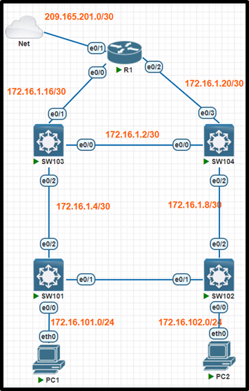
Refer to the topology. All physical cabling is in place. Configure local users accounts. modify the Named ACL (NACL). and configure DHCP Snooping. The current contents of the NACL must remain intact.
* Configure a local account on Sw103 with telnet access only on virtual ports 0-4. Use the following information:
1. Username: devnet
2. Password: access8cli
3. Algorithm type: SHA256
4. Privilege level: Exec mode
« Using the minimum number of ACEs. modify the existing NACL “INTERNET_ACL” to control network traffic destined for the Internet. and apply the ACL on R1:
1. Allow HTTPS from 172.16.0.0/16
2. Allow Telnet only for VLAN 101
3. Restrict all other traffic and log the ingress interface. source MAC address. the packet’s source and destination IP addresses. and ports
» Configure Sw101:
1. Enable DNCP Snooping for VLAN 101
2. Disable DHCP Option-82 data insertion
3. Enable DHCP Snooping MAC address verification
Configuration
SW103:
SW103>en
SW103#config t
SW103(config)# username devnet privilege 15 algorithm-type sha256 secret access8cli
SW103(config)# line vty 0 4
SW103(config-line)#login local
SW103(config-line)#transport input telnet
SW103(config-line)#end
SW103# wr
R1:
R1>en
R1#config t
R1(config)# ip access-list extended INTERNET_ACL
R1(config-ext-nacl)#permit tcp 172.16.0.0 0.0.255.255 any eq 443
R1(config-ext-nacl)#permit tcp 172.16.101.0 0.0.0.255 any eq telnet
R1(config-ext-nacl)#deny ip any any log
R1(config-ext-nacl)#end
R1#wr
SW101:
Sw101>en
Sw101#config t
Sw101(config)#ip dhcp snooping vlan 101
Sw101(config)#no ip dhcp snooping information option
Sw101(config)#ip dhcp snooping verify mac-address
Sw101(config)#end
Sw101#wr
Access List port-security 16 OLD
Refer to the topology. All physical cabling is in place. Configure a local user account, a Named ACL (NACL), and security.
* Configure a local account on Sw101 with telnet access only on virtual ports 0-4. Use the following information:
1. Username: netops
2. Password: ipsec4all
3. Algorythm: “Vigenere”
4. Privilege level: Exec mode
* Configure and apply a single NACL on Sw103 using the following:
1. name: ENT_ACL
2. Restrict only PC1 on VLAN 10 from pinging PC2
3. Allow only PC1 on VLAN 10 to telnet to R14 (172.16.30.2)
4. Prevent all other devices from telnetting from VLAN 10
5. Allow all other network traffic from VLAN10
* Configure security on interface Ethernet 0/0 of Sw102:
1. Set the maximum number of secure MAC addresses to two
2. Ensure that the port discards the packet, counts the number of violations and sends a syslog message
3 Allow secure mac addresses to be learned dynamically
Configuration
SW101:
Sw101>en
Sw101#conf t
Sw101(config)#username netops privilege 15 password ipsec4all
Sw101(config)#service password-encryption
SW101(config)# line vty 0 4
SW101(config-line)#login local
SW101(config-line)#transport input telnet
SW101(config-line)#end
SW101# wr
SW102:
Sw102>en
Sw102#config t
Sw102(config)#int f0/3
Sw102(config-if)#switchport port-security
Sw102(config-if)#switchport port-security maximum 2
Sw102(config-if)# switchport port-security violation restrict
Sw102(config)#end
Sw102#wr
SW103:
Sw103>en
Sw103#config t
ip access-list extended ENT_ACL
deny icmp host 172.16.10.10 host 172.16.20.10
permit tcp host 172.16.10.10 host 172.16.30.2 eq telnet
deny tcp 172.16.10.0 0.0.0.255 any eq telnet
permit ip 172.16.10.0 0.0.0.255 any
exit
Int vlan 10
Ip access-group ENT_ACL in
Sw103#wr
Access List port-security LAB 17 OLD
Tasks
Task 1. Configure a local account on Sw101 with telnet access only on virtual ports 0-4. Use the following information:
+ Username: support
+ Password: max2leam
+ Privilege level: Exec mode
Task 2. Configure and apply a single NACL on Sw101 using the following:
+ Name: ENT_ACL
+ Restrict only PC2 on VLAN 200 from pinging PC1
+ Allow only PC2 on VLAN 200 to telnet to Sw101
+ Prevent all other devices from telnetting from VLAN 200
+ Allow all other network traffic from VLAN 200
Task 3. Configure security on interface Ethernet 0/0 of Sw102:
+ Set the maximum number of secure MAC addresses to four.
+ Drop packets with unknown source addresses until the number of secure MAC addresses drops below the configured maximum value. No notification action is required.
+ Allow secure MAC addresses to be learned dynamically.
Configuration
username support privilege 15 password max2leam
line vty 0 4
transport input telnet
login local
ip access-list extended ENT_ACL
deny icmp host 192.168.200.10 host 192.168.100.10
permit tcp host 192.168.200.10 host 192.168.100.1 eq telnet
deny tcp 192.168.200.0 0.0.0.255 any eq telnet
permit ip any any
interface vlan 200
ip access-group ENT_ACL in
int F0/10
switchport port-security
switchport port-security maximum 4
switchport port-security violation protect
switchport port-security mac-address sticky
Static Routing LAB 18 OLD
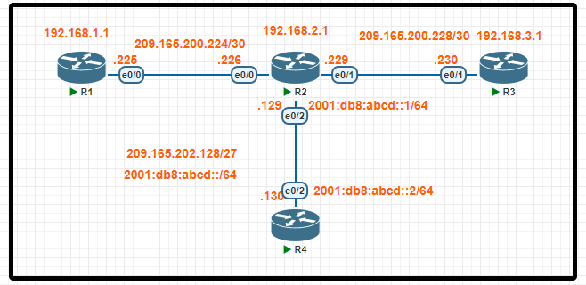
Tasks:
Connectivity between four routers has been established. IP connectivity must be configured in the order presented to complete the implementation. No dynamic routing protocols are included.
1. Configure static routing using host routes to establish connectivity from router R3 to the router R1 Loopback address using the source IP of 209.165.200.230.
2. Configure an IPv4 default route on router R2 destined for router R4.
3. Configure an IPv6 default router on router R2 destined for router R4
Configuration
R3(config)#ip route 192.168.1.1 255.255.255.255 209.165.200.229
R2(config)#ip route 192.168.1.1 255.255.255.255 209.165.200.225
R1(config)#ip route 209.165.200.230 255.255.255.255 209.165.200.226
Verification
R3#ping 192.168.1.1
.!!!!
Task 2. Configure an IPv4 default route on router R2 destined for router R4
R2(config)#ip route 0.0.0.0 0.0.0.0 209.165.202.130
Task 3. Configure an IPv6 default router on router R2 destined for router R4
R2(config)#ipv6 route ::/0 2001:db8:abcd::2
IPv6 routing LAB 19 OLD

All physical cabling is in place. Configurations should ensure that connectivity is established end-to-end.
- Configure a route on R1 to ensure that R1 prefers R2 to reach the 2001:db8:41::/64 network
- Configure a floating route on R1, and ensure that R1 uses R3 to reach the 2001:db8:41::/64 network if the connection between R1 and R2 is down
- Ping and traceroute should be working
Configuration
R1:
R1> en
R1# config t
R1(config)# ipv6 route 2001:db8:41::/64 2001:db8:12::2
R1(config)# ipv6 route 2001:db8:41::/64 2001:db8:13::3 2
R1(config)#end
R1#wr
R2:
R2> en
R2# config t
R2(config)# ipv6 route 2001:db8:41::/64 2001:db8:24::4
R2(config)#end
R2#wr
R3:
R3> en
R3# config t
R3(config)# ipv6 route 2001:db8:41::/64 2001:db8:34::4
R3(config)#end
R3#wr
R4:
R4>en
R4# config t
R4(config)# ipv6 route 2001:db8:12::/64 2001:db8:24::2
R4(config)# ipv6 route 2001:db8:13::/64 2001:db8:34::3
R4(config)#end
R4#wr
IPv4 static, default routing 20 OLD

Tasks
All physical cabling is in place. Router R4 and PC1 are fully configured and inaccessible. R4’s WAN interfaces use 4 in the last octet for each subnet. Configurations should ensure that connectivity is established end-to-end.
1. Configure static routing to ensure R1 prefers the path through R2 to reach only PC1 on R4’s LAN
2. Configure static routing that ensures traffic sourced from R1 will take an alternate path through R3 to PC1 in the event of an outage along the primary path
3. Configure default routes on R1 and R3 to the Internet using the least number of hops
Configuration
R1:
R1> en
R1#config t
R1(config)# ip route 10.0.41.10 255.255.255.255 10.0.012.2
R1(config)# ip route 10.0.41.10 255.255.255.255 10.0.013.3 2
R1(config)# ip route 0.0.0.0 0.0.0.0 10.0.13.3
R1(config)# end
R1#wr
R3:
R3>en
R3#config t
R3(config)# ip route 0.0.0.0 0.0.0.0 209.165.201.1
R3(config)#end
R3#wr
IPv4 static and default LAB 21 OLD
Tasks
All physical cabling is in place. Routers R3 and R4 are fully configured and inaccessible. Configure static routes for various connectivity to the ISP and the LAN that resides on R4.
1. Configure a route on R1 to ensure that R1 prefers R2 when traffic is destined to the server only.
2. Configure a default route on R2 to the ISP
3. Configure a route on R1 to ensure that R1 will use R2 for the R4 LAN if the link fails between R3 and R4
4. Configure a route on R1 to ensure that R1 prefers R3 when traffic its destined to the R4 LAN at 10.0.41.0/24
Configuration
R1:
R1>en
R1(config)# ip route 10.0.41.10 255.255.255.255 10.0.12.2
R1(config)# ip route 10.0.41.0 255.255.255.0 10.0.13.3
R1(config)# ip route 10.0.41.0 255.255.255.0 10.0.12.2 2
R1(config)# end
R1#wr
R2:
R2>en
R2(config)# ip route 0.0.0.0 0.0.0.0 209.165.200.225
R2(config)# end
R2#wr
VLAN and CDP LAB 22 OLD

R1 has been pre-configured with all the necessary commands. All physical cabling is in place and verified. Connectivity from PC1, PC3, and the Server must be established to the switches. and each port must only allow one VLAN.
- Configure the VLAN connecting to the switch port for PC3 with the name “SALES”
- Configure the switch port connecting to Server1
- Configure the switch port connecting to PC3.
- Ensure R1 discovers SW-1 via the Cisco proprietary neighbor discovery protocol and all other devices on the network are unable to discover SW-1
Configuration
SW-1:
SW-1>en
SW-1# Config t
Sw-1(config)# cdp run
Sw-1(config)# int range f0/1-2
Sw-1(config-if-range)# no cdp enable
Sw-1(config-if-range)# end
SW-1# wr
SW-2:
SW-2>en
SW-2# Config t
SW-2(config)# vlan 20
SW-2(config-vlan)# vlan 30
SW-2(config-vlan)# name SALES
SW-2(config-vlan)# exit
SW-2(config)# int f0/2
SW-2(config-if) # switchport mode access
SW-2(config-if) # switchport access vlan 20
SW-2(config)# int f0/3
SW-2(config-if) # switchport mode access
SW-2(config-if) # switchport access vlan 30
SW-2# wr
Static Routing LAB 23 OLD
Tasks
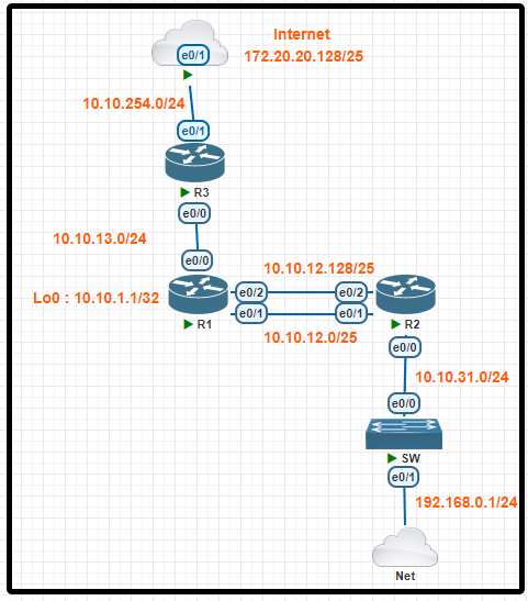
IP connectivity and OSPF are preconfigured on all devices where necessary. Do not make any changes to the IP addressing or OSPF. The company policy uses connected interfaces and next hops when configuring static routes except for load balancing or redundancy without floating static. Connectivity must be established between subnet 172.20.20.128/25 on the Internet and the LAN at 192.168.0.0/24 connected to SW1:
1. Configure reachability to the switch SW1 LAN subnet in router R2.
2. Configure default reachability to the Internet subnet in router R1.
3. Configure a single static route in router R2 to reach to the Internet subnet considering both redundant links between routers R1 and R2. A default route is NOT allowed in router R2.
4. Configure a static route in router R1 toward the switch SW1 LAN subnet where the primary link must be through Ethernet0/1, and the backup link must be through Ethernet0/2 using a floating route. Use the minimal administrative distance value when required.
Configuration
R2(config)#ip route 192.168.0.0 255.255.255.0 10.10.31.1
R2#ping 192.168.0.1
.!!!!
R1(config)#ip route 0.0.0.0 0.0.0.0 10.10.13.3
R1#ping 172.20.20.129
.!!!!
R2(config)#ip route 172.20.20.128 255.255.255.128 10.10.1.1
R2#ping 172.20.20.129
.!!!!
R1(config)#ip route 192.168.0.0 255.255.255.0 10.10.12.2
R1(config)#ip route 192.168.0.0 255.255.255.0 10.10.12.130 2
R1#ping 192.168.0.1
.!!!!
Remember to save all devices:
R1, R2, R3#Wr

Tasks
Physical connectivity is implemented between the two Layer 2 switches, and the network connectivity between them must be configured.
1. Configure an LACP EtherChannel and number it as 44; configure it between switches SW1 and SW2 using interfaces Ethernet0/0 and Ethernet0/1 on both sides. The LACP mode must match on both ends.
2. Configure the EtherChannel as a trunk link.
3. Configure the trunk link with 802.1q tags.
4. Configure VLAN ‘MONITORING’ as the untagged VLAN of the EtherChannel.
Configuration
SW1
enable
conf t
interface range f0/1-2
channel-group 44 mode active
exit
interface port-channel 44
shutdown
switchport trunk encapsulation dot1q
switchport mode trunk
switchport trunk native vlan 746
no shutdown
end
wr
SW2>enable
conf t
interface range f0/1-2
channel-group 44 mode active
exit
interface port-channel 44
shutdown
switchport trunk encapsulation dot1q
switchport mode trunk
switchport trunk native vlan 746
no shutdown
end
wr
VLAN Configuration And Trunk LAB 25 OLD

Tasks
The company requires only the designated VLANs to be configured on their respective switches and permitted across any links between switches for security purposes.
Do not modify or delete VTP configurations. The network needs two user-defined VLANs configured:
VLAN 202: MARKETING VLAN 303: FINANCE
1. Configure the VLANs on the designated switches and assign them as access ports to the interfaces connected to the PCs.
2. Configure the e0/2 interfaces on Sw1 and Sw2 as 802.1q trunks with only the required VLANs permitted.
3. Configure the e0/3 interfaces on Sw2 and Sw3 as 802.1q trunks with only the required VLANs permitted.
SW1:
SW1>en
SW 1#config t
SW1(config)#vlan 303
SW1(config-vlan)#name FINANCE
SW1(config-vlan)#int f0/2
SW1 (config-if)#switchport trunk encapsulation dot1q
SW1(config-if)#switchport mode trunk
SW1(config-if)#switchport trunk allowed vlan 303
SW1(config-if)#int f0/1
SW1(config-if)#switchport mode access
SW1(config-if)#switchport access vlan 303
SW1(config-if)#end
SW1#wr
Configuration
SW2:
SW2>en
SW2# config t
SW2(config)#vlan 202
SW2(config-vlan)#name MARKETING
SW2(config-vlan)#vlan 303
SW2(config-vlan)#name FINANCE
SW2(config-vlan)#int f0/2
SW2(config-if)#switchport trunk encapsulation dot1q
SW2(config-if)#switchport mode trunk
SW2(config-if)#switchport trunk allowed vlan 303
SW2(config-if)#int f0/3
SW2(config-if)#switchport trunk encapsulation dot1q
SW2(config-if)#switchport mode trunk
SW2(config-if)#switchport trunk allowed vlan 202,303
SW2(config-if)#int f0/1
SW2(config-if)#switchport mode access
SW2(config-if)#switchport access vlan 202
SW2(config-if)#end
SW2#wr
SW3:
SW3>en
SW3#config t
SW3(config)#vlan 202
SW3(config-vlan)#name MARKETING
SW3(config-vlan)#vlan 303
SW3(config-vlan)#name FINANCE
SW3(config-vlan)#int f0/3
SW3(config-if)#switchport trunk encapsulation dot1q
SW3(config-if)#switchport mode trunk
SW53(config-if)#switchport trunk allowed vlan 202,303
SW3(config-if)#int f0/2
SW3(config-if)#switchport mode access
SW3(config-if)#switchport access vlan 202
SW3(config-if)#int f0/1
SW3(config-if)#switchport mode access
SW3(config-if)#switchport access vlan 303
SW3(config-if)#end
SW3#wr
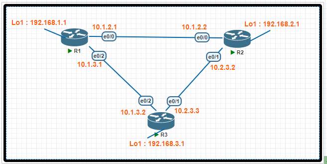
OSPF LAB 26 OLD

Tasks
IP connectivity between the three routers is configured. OSPF adjacencies must be established.
1. Configure R1 and R2 Router IDs using the interface IP addresses from the link that is shared between them.
2. Configure the R2 links with a max value facing R1 and R3.R2 must become the DR.R1 and R3 links facing R2 must remain with the default OSPF configuration for DR election. Verify the configuration after clearing the OSPF process.
3. Using a host wildcard mask, configure all three routers to advertise their respective Loopback1 networks.
4. Configure the link between R1 and R3 to disable their ability to add other OSPF routers.
Configuration
R1>en
R1# config t
R1(config)# interface G0/1
R1(config-if)# ip ospf network point-to-point
R1(config-if)# exit
R1(config)# router ospf 1
R1(config-router)# router-id 10.10.12.1
R1(config-router)# network 192.168.1.1 0.0.0.0 area 0
R1(config-router)# end
R1# clear ip ospf process
yes
R1# write
R2>en
R2# config t
R2(config)# interface G0/0
R2(config-if)# ip ospf priority 255
R2(config-if)# interface G0/2
R2(config-if)# ip ospf priority 255
R2(config-if)# exit
R2(config)# router ospf 1
R2(config-router)# router-id 10.10.12.2
R2(config-router)# network 192.168.2.2 0.0.0.0 area 0
R2(config-router)# end
R2# clear ip ospf process
yes
R2# write
R3>en
R3# config t
R3(config)# interface G0/1
R3(config-if)# ip ospf network point-to-point
R3(config-if)# exit
R3(config)# router ospf 1
R3(config-router)# network 192.168.3.3 0.0.0.0 area 0
R3(config-router)# end
R3# clear ip ospf process
yes
R3# write
NAT DHCP NTP SSH LAB 27 OLD

Tasks
Services must be configured in the order presented to complete the implementation.
1. Configure dynamic one-to-one address mapping on R2 using a standard list named XLATE, which allows all traffic to translate the source address of R3 to a pool named test_pool using the 10.10.10.0/24 network for traffic sent from R3 to R1. Avoid using an NVI configuration. Verify reachability by sending a ping to 192.168.100.1 from R3.
2. Configure R3 to dynamically receive an IP address on Ethernet0/2 from the DHCP server.
3. Configure R1 as an NTP server and R2 as a client, not as a peer, using the IP address 10.1.2.1.
4. Configure SSH access from R1 to R3, while excluding access via other remote connection protocols using the user root and password s3cret on router R3 using RSA. Verify connectivity from router R1 to R3 using a destination address assigned to interface E0/2 on R3.
Configuration
R2>enable
R2#conf t
R2(config)# ip access-list standard XLATE
R2(config-std-nacl)#permit 10.2.3.3
R2(config-std-nacl)#permit 192.168.3.1
R2(config-std-nacl)#permit 10.1.3.11
R2(config-std-nacl)#exit
R2(config)# interface G0/1
R2(config-if)#ip nat inside
R2(config-if)#exit
R2(config)#interface G0/0
R2(config-if)#ip nat outside
R2(config-if)#exit
R2(config)#ip nat pool test_pool 10.10.10.1 10.10.10.254 netmask 255.255.255.0
R2(config)#ip nat inside source list XLATE pool test_pool
R2(config)#exit
R2(config)#ntp server 10.1.2.1
R2#wr
R3:: ping 192.168.100.1
R3(config)#interface G0/2
R3(config-if)#ip address dhcp
R3(config-if)#exit
R1#config t
R1(config)#ntp master 1
R1(config)#exit
R1#wr
R3(config)#ip domain name cisco.com
R3(config)#line vty 0 4
R3(config-line)#transport input ssh
R3(config-line)#login local
R3(config-line)#exit
R3(config)#username root password s3cret
R3(config)#crypto key generate rsa
R3(config)#exit
R3#wr